WO2024117271A2 - 物品収納箱 - Google Patents
物品収納箱 Download PDFInfo
- Publication number
- WO2024117271A2 WO2024117271A2 PCT/JP2024/012307 JP2024012307W WO2024117271A2 WO 2024117271 A2 WO2024117271 A2 WO 2024117271A2 JP 2024012307 W JP2024012307 W JP 2024012307W WO 2024117271 A2 WO2024117271 A2 WO 2024117271A2
- Authority
- WO
- WIPO (PCT)
- Prior art keywords
- storage box
- item storage
- cut
- box according
- main body
- Prior art date
Links
- 238000003860 storage Methods 0.000 title claims abstract description 235
- 239000003205 fragrance Substances 0.000 claims description 24
- 239000000428 dust Substances 0.000 abstract description 8
- 238000005452 bending Methods 0.000 abstract description 5
- 239000000123 paper Substances 0.000 description 27
- 230000001965 increasing effect Effects 0.000 description 25
- 238000010586 diagram Methods 0.000 description 7
- 230000000694 effects Effects 0.000 description 7
- 238000004519 manufacturing process Methods 0.000 description 4
- 230000001737 promoting effect Effects 0.000 description 4
- 238000005728 strengthening Methods 0.000 description 4
- 239000002699 waste material Substances 0.000 description 3
- 230000007613 environmental effect Effects 0.000 description 2
- 238000003780 insertion Methods 0.000 description 2
- 230000037431 insertion Effects 0.000 description 2
- 238000000034 method Methods 0.000 description 2
- 230000001151 other effect Effects 0.000 description 2
- 239000002985 plastic film Substances 0.000 description 2
- 229920006255 plastic film Polymers 0.000 description 2
- 230000002708 enhancing effect Effects 0.000 description 1
- 239000000463 material Substances 0.000 description 1
- 238000012986 modification Methods 0.000 description 1
- 230000004048 modification Effects 0.000 description 1
- 239000004033 plastic Substances 0.000 description 1
Images


Classifications
-
- B—PERFORMING OPERATIONS; TRANSPORTING
- B65—CONVEYING; PACKING; STORING; HANDLING THIN OR FILAMENTARY MATERIAL
- B65D—CONTAINERS FOR STORAGE OR TRANSPORT OF ARTICLES OR MATERIALS, e.g. BAGS, BARRELS, BOTTLES, BOXES, CANS, CARTONS, CRATES, DRUMS, JARS, TANKS, HOPPERS, FORWARDING CONTAINERS; ACCESSORIES, CLOSURES, OR FITTINGS THEREFOR; PACKAGING ELEMENTS; PACKAGES
- B65D83/00—Containers or packages with special means for dispensing contents
- B65D83/08—Containers or packages with special means for dispensing contents for dispensing thin flat articles in succession
Definitions
- the present invention relates to an item storage box in which multiple items are stored in a stacked state.
- Patent Document 1 An example of a conventional item storage box is described in Patent Document 1.
- the item storage box described in this document has a box-shaped main body consisting of a bottom portion, side portions, and a top portion, and stores a plurality of items (tissue paper) in a stacked state.
- the top portion is provided with an outlet forming portion through which an outlet for the items is formed.
- the outlet forming portion has wavy perforations formed along a center line that divides the top portion in half in the short direction.
- the parts on either side of the cut can be folded diagonally upwards to form a gap between the folded pieces that serves as an access port.
- the gap (access port) between the folded pieces becomes wider. If the access port is too wide, there is a problem in that dust can easily enter the main body through the access port.
- the present invention was made in consideration of the above problems, and aims to provide an item storage box that can prevent dust from entering the main body through the removal opening.
- the item storage box according to the present invention is an item storage box in which a plurality of items are stored in a stacked state, and is equipped with a box-shaped main body having an outlet forming portion on the upper surface thereof through which an outlet for the items is formed, and the outlet forming portion has first and second folding pieces that are folded diagonally upward on the upper surface portion so that their inner faces face each other, and a first folding line for folding the first folding piece, and the first folding line is characterized in that it has a curved shape that bulges outward from the first folding piece.
- This item storage box is provided with first and second folding pieces that are folded diagonally upward so that their inner faces face each other.
- first and second folding pieces By folding the first and second folding pieces, a gap that serves as an access port can be created between the first folding piece and the second folding piece.
- the first folding piece is folded along the first folding line, which has a curved shape that bulges outward from the first folding piece.
- a force acts on the first folding piece that tries to return it to its original state when it is folded along the first folding line. This makes it possible to prevent the folding angle of the first folding piece from becoming too large.
- the present invention provides an item storage box that can prevent dust from entering the main body through the outlet.
- FIG. 1 is a plan view showing a first embodiment of an item storage box according to the present invention; FIG. A plan view showing a portion of the cut line 42.
- FIG. 2 is a perspective view showing the item storage box 1 when in use.
- 5 is a diagram for explaining the structure of the end face taken along line VV in FIG. 4.
- FIG. 4 is a perspective view showing a second embodiment of an item storage box according to the present invention.
- FIG. 4 is a perspective view showing a second embodiment of an item storage box according to the present invention.
- FIG. 4 is a side view showing a second embodiment of an item storage box according to the present invention.
- FIG. 11 is a perspective view showing the main body 110 after deformation.
- FIG. 11 is a plan view showing the main body 110 after deformation.
- FIG. 11 is a plan view showing the main body 110 after deformation.
- FIG. 11 is a side view showing the main body 110 after deformation. 11 is a diagram for explaining the structure of the end face taken along line AA in FIG. 10. 11 is a side view for explaining an example in which a fragrance section 112 is provided in a main body 110.
- FIG. 13 is a plan view illustrating a modified example of the tongue piece 172.
- FIG. 11 is a side view illustrating a modified example of a folding line 133.
- FIG. 13 is a side view for explaining another modified example of the cut line 160.
- FIG. 13 is a side view for explaining another modified example of the cut line 160.
- FIG. 13 is a side view for explaining another modified example of the cut line 160.
- FIG. 13 is a side view for explaining another modified example of the cut line 160.
- FIG. 13 is a side view for explaining another modified
- FIG. 13 is a side view for explaining another modified example of the cut line 160.
- FIG. FIG. 11 is a perspective view showing a third embodiment of an item storage box according to the present invention.
- FIG. 11 is a perspective view showing a third embodiment of an item storage box according to the present invention.
- FIG. 11 is a bottom view showing a third embodiment of an item storage box according to the present invention.
- FIG. 11 is a side view showing a third embodiment of an item storage box according to the present invention.
- FIG. 11 is a side view showing a third embodiment of an item storage box according to the present invention.
- FIG. 11 is a side view showing a third embodiment of an item storage box according to the present invention.
- FIG. 11 is a perspective view showing the main body 210 after deformation.
- FIG. 11 is a perspective view showing the main body 210 after deformation.
- FIG. 11 is a perspective view showing the main body 210 after deformation.
- FIG. 11 is a perspective view showing the main body 210 after
- FIG. 11 is a plan view showing the main body 210 after deformation.
- FIG. 13 is a bottom view showing the main body 210 after deformation.
- FIG. 29 is a diagram for explaining the structure of the end face taken along line BB in FIG. 28. 2 is a diagram for explaining an example in which a fragrance section 212 is provided in a main body 210.
- FIG. FIG. 13 is a plan view illustrating a modified example of a segment 272.
- 13 is a side view illustrating a modified example of the cut line 262.
- FIG. 13 is a side view illustrating a modified example of the cut line 264.
- FIG. 13 is a side view illustrating a modified example of a slit portion 282.
- FIG. 13 is a side view illustrating a modified example of a slit portion 284.
- 13 is a side view illustrating another modified example of the cut line 262.
- FIG. 13 is a side view illustrating another modified example of the cut line 264.
- FIG. 13 is a side view illustrating another modified example of the cut line 262.
- FIG. 13 is a side view illustrating another modified example of the cut line 262.
- FIG. 13 is a side view illustrating another modified example of the cut line 264.
- FIG. 13 is a perspective view illustrating a modified example of the cut line 250.
- FIG. 13 is a perspective view illustrating another modified example of the cut line 250.
- FIG. 13 is a perspective view for explaining another modified example of the cut line 250.
- FIG. 11 is a plan view showing an outlet forming portion 20 according to a modified example.
- FIG. 11 is a plan view showing an outlet forming portion 20 according to another modified example.
- FIG. 1 is a plan view showing a first embodiment of an item storage box according to the present invention.
- the item storage box 1 is an item storage box in which a plurality of items are stored in a stacked state, and has a main body 10. Examples of the items include tissue paper, paper towels, kitchen paper, gloves, and masks. In this embodiment, the item is tissue paper.
- the main body 10 is box-shaped. Specifically, the main body 10 is rectangular. An outlet forming section 20 is provided on the top surface 12 of the main body 10. The top surface 12 is rectangular in plan view. An outlet for removing items is formed in the outlet forming section 20.
- the outlet forming section 20 is horizontally long. That is, the dimension of the outlet forming section 20 in the long side direction of the top surface 12 (left and right direction in FIG. 1) is larger than the dimension of the outlet forming section 20 in the short side direction of the top surface 12 (up and down direction in FIG. 1).
- the main body 10 is flexible. For example, paper such as cardboard can be used as the material of the main body 10. It is preferable that the item storage box 1 is made of paper only.
- the outlet forming section 20 has a folding piece 22 (first folding piece), a folding piece 24 (second folding piece), a fold line 32 (first fold line), a fold line 34 (second fold line), a cut line 42 (boundary cut line), a cut line 44, and a cut line 46.
- the folding pieces 22 and 24 are folded diagonally upward from the top surface section 12 so that their inner faces face each other. In other words, the folding pieces 22 and 24 have a double door structure.
- Figure 1 shows the folding pieces 22 and 24 in an unfolded state.
- the fold line 32 is a fold line for folding the folding piece 22.
- the folding piece 22 is folded along the fold line 32.
- the fold line 32 coincides with the rear end edge of the folding piece 22 (the portion of the periphery of the folding piece 22 that is not separated from the top surface portion 12 even after the folding piece 22 is folded).
- the fold line 32 is curved and bulges outward from the folding piece 22.
- the apex 32a of the fold line 32 exists on the center line L1 that bisects the top surface portion 12 in the long side direction.
- the apex 32a is the point closest to the long side 12a of the top surface portion 12 (the long side on the fold line 32 side).
- the fold line 32 is linearly symmetrical with respect to the center line L1. It is preferable that the fold line 32 describes a circular arc or an elliptical arc.
- FIG. 2 is a plan view showing the fold line 32.
- the curve ratio of the fold line 32 is preferably 1.9% to 9.7%, and more preferably 1.9% to 4.8%.
- the curve ratio is a numerical value reflecting the magnitude of the curve, and is defined as the value obtained by dividing the length d1 by the length d2.
- the length d1 is equal to the length of the short side of the smallest rectangle R1 that can contain the entire fold line 32.
- the length d1 is, for example, 2 mm to 20 mm.
- the length d2 is equal to the length of the long side of the rectangle R1.
- the short side and long side of the rectangle R1 are parallel to the short side and long side of the top surface portion 12, respectively.
- the length d2 is, for example, 120 mm to 200 mm.
- the fold line 34 is a fold line for folding the folding piece 24. That is, the folding piece 24 is folded along the fold line 34.
- the fold line 34 coincides with the rear end edge of the folding piece 24 (the portion of the periphery of the folding piece 24 that is not separated from the upper surface portion 12 even after the folding piece 24 is folded).
- the fold line 34 is curved and bulges outward from the folding piece 24.
- the apex 34a of the fold line 34 is located on the center line L1.
- the apex 34a is the point closest to the long side 12b (the long side on the fold line 34 side) of the upper surface portion 12.
- the fold line 34 is symmetrical with respect to the center line L1.
- the fold line 34 describes a circular arc or an elliptical arc.
- the fold line 34 has a shape congruent with the fold line 32.
- the fold line 34 is arranged symmetrically with the fold line 32 with respect to the center line L2 that bisects the upper surface portion 12 in the short side direction.
- the curve rate of the fold line 34 is preferably 1.9% to 9.7%, and more preferably 1.9% to 4.8%.
- the definition of the curve rate of the fold line 34 is the same as the definition of the curve rate of the fold line 32.
- the cut line 42 is located at the boundary between the folded pieces 22 and 24. Therefore, the cut line 42 coincides with the leading edge of the folded piece 22 (the portion of the periphery of the folded piece 22 that faces the outlet) and the leading edge of the folded piece 24 (the portion of the periphery of the folded piece 24 that faces the outlet).
- the cut line 42 is a perforation.
- the cut line 42 is wavy and extends in the direction of the long side of the top surface portion 12.
- the cut line 42 is formed along a single continuous wavy line.
- the cut line 42 has a shape that does not have corners.
- the cut line 42 is made up of only curves. It is preferable that the cut line 42 describes a sine curve.
- FIG. 3 is a plan view showing a portion of the cut line 42.
- the half wavelength d3 of the cut line 42 is preferably 3 mm or more and 10 mm or less, and more preferably 3 mm or more and 5 mm or less.
- the half wavelength d3 is half the wavelength of the cut line 42.
- the total amplitude d4 of the cut line 42 is preferably 3 mm or more and 10 mm or less, and more preferably 3 mm or more and 5 mm or less.
- the total amplitude d4 is twice the amplitude (single amplitude) of the cut line 42.
- the cut line 44 connects one end of the fold line 32 to one end of the fold line 34.
- the cut line 44 coincides with the side edge of the folded piece 22 (the part of the periphery of the folded piece 22 other than the rear edge or the front edge) and the side edge of the folded piece 24 (the part of the periphery of the folded piece 24 other than the rear edge or the front edge).
- the cut line 44 is a perforation.
- the cut line 44 is in a straight line parallel to the short side of the top surface portion 12.
- the cut line 46 connects the other end of the fold line 32 to the other end of the fold line 34.
- the cut line 46 coincides with the side edge of the folded piece 22 and the folded piece 24.
- the cut line 46 is a perforation.
- the cut line 46 is in a straight line parallel to the short side of the top surface portion 12.
- the cut line 46 is arranged symmetrically with the cut line 44, with the center line L1 as the axis of symmetry.
- FIG. 4 is a perspective view showing the item storage box 1 when in use.
- FIG. 5 is a diagram for explaining the structure of the end face along line V-V in FIG. 4. Items are not shown in FIGS. 4 and 5.
- the item storage box 1 is provided with folding pieces 22 and 24 that are folded diagonally upward so that their inner surfaces face each other.
- a gap 50 that serves as an outlet can be created between the folding pieces 22 and 24.
- the folding pieces 22 are folded along the fold lines 32, which are curved and bulge outward from the folding pieces 22.
- a force returns force acts on the folding pieces 22 that are folded along the fold lines 32 to return them to their original state (unfolded state). This makes it possible to prevent the folding angle of the folding pieces 22 from becoming too large. Therefore, an item storage box 1 that can prevent dust from entering the main body 10 through the outlet can be realized.
- the fold 34 also has a curved shape that bulges outward from the folding piece 24.
- a restoring force also acts on the folding piece 24 that is folded along the fold 34. This makes it possible to prevent the folding angle of the folding piece 24 from becoming too large. This further prevents dust from entering the main body 10 through the removal opening.
- the mechanism by which the curved fold line 32 restricts the bending angle of the folding piece 22 will now be explained in detail. If the main body 10 is rigid (not flexible), the folding piece 22 cannot be bent along a curve. In contrast, in the item storage box 1, the main body 10 is flexible, so even if the fold line 32 is curved, the folding piece 22 can be bent to a certain angle due to the flexure of the main body 10. At this time, a return force acts on the folding piece 22 due to the restoring force of the main body 10. This restricts the bending angle of the folding piece 22. The same applies to the mechanism by which the curved fold line 34 restricts the bending angle of the folding piece 24.
- the fold line 32 forms a circular or elliptical arc, it contributes to improving the aesthetics of the outlet forming section 20 and therefore the item storage box 1.
- the fold line 34 forms a circular or elliptical arc, it contributes to improving the aesthetics of the outlet forming section 20 and therefore the item storage box 1.
- Increasing the curve rate of the fold line 32 is advantageous in strengthening the return force acting on the folding piece 22. From this perspective, it is preferable that the curve rate of the fold line 32 is 1.9% or more. On the other hand, if the curve rate of the fold line 32 is too large, the return force will be excessively strong, which may make it difficult to remove the item from the removal opening. From this perspective, it is preferable that the curve rate of the fold line 32 is 9.7% or less, and more preferably 4.8% or less.
- Increasing the curve rate of the fold line 34 is advantageous in strengthening the return force acting on the folding piece 24. From this perspective, it is preferable that the curve rate of the fold line 34 is 1.9% or more. On the other hand, if the curve rate of the fold line 34 is too large, the return force will be excessively strong, which may make it difficult to remove the item from the removal opening. From this perspective, it is preferable that the curve rate of the fold line 34 is 9.7% or less, and more preferably 4.8% or less.
- the cut line 42 is wavy. In this case, unevenness is created at the tip edges of the folding pieces 22 and 24. This can strengthen the holding power of the folding pieces 22 and 24 against the item.
- the cut line 42 has a shape without any corners. This makes it less likely that an item will get caught on the leading edge of the folding piece 22 and the folding piece 24 when being removed, making it easier to remove the item smoothly.
- cut line 42 forms a sine curve, it helps to improve the aesthetic appearance of the outlet forming portion 20 and therefore the item storage box 1.
- the half wavelength d3 of the cut line 42 is advantageous in strengthening the holding power of the folding pieces 22 and 24 against an object, since the unevenness of the tip edges of the folding pieces 22 and 24 becomes finer.
- the half wavelength d3 is preferably 10 mm or less, and more preferably 5 mm or less.
- the half wavelength d3 is preferably 3 mm or more.
- the total amplitude d4 of the cut line 42 increases the unevenness difference at the tip edges of the folded pieces 22 and 24, which is advantageous in strengthening the holding power of the folded pieces 22 and 24 against the item. From this perspective, it is preferable that the total amplitude d4 is 3 mm or more. On the other hand, if the total amplitude d4 is too large, the item will penetrate too deeply into the recess, preventing smooth removal of the item. From this perspective, it is preferable that the total amplitude d4 is 10 mm or less, and more preferably 5 mm or less.
- the item storage box 1 no plastic film is provided at the outlet. This contributes to reducing waste plastic, so the item storage box 1 also has the advantage of being environmentally friendly.
- FIGS. 6 and 7 are perspective views showing a second embodiment of an item storage box according to the present invention.
- FIG. 8 is a side view showing a second embodiment of an item storage box according to the present invention.
- the item storage box 2 is an item storage box in which multiple items are stored in a stacked state, and includes a main body 110.
- the main body 110 is box-shaped and is composed of a bottom surface portion 120, a side surface portion 132 (first side surface portion), a side surface portion 134 (second side surface portion), a side surface portion 136 (third side surface portion), a side surface portion 138 (fourth side surface portion), and a top surface portion 140.
- the main body 110 is rectangular parallelepiped-shaped.
- Figures 6 and 7 are oblique views seen from the top surface portion 140 side and the bottom surface portion 120 side, respectively.
- Figure 8 is a side view seen from the side surface portion 134 side.
- the side surface portion 132 and the side surface portion 134 face each other.
- the side surface portion 136 and the side surface portion 138 also face each other.
- the widths of the side surface portion 132 and the side surface portion 134 are greater than the widths of the side surface portion 136 and the side surface portion 138.
- the top surface portion 140 is provided with an outlet forming portion 20.
- the configuration of the outlet forming portion 20 is as described in the first embodiment. However, in this embodiment, detailed illustration of the outlet forming portion 20 is omitted.
- the main body 110 is configured so that it can be deformed into a bottom-up state.
- the main body 110 can be made of, for example, cardboard or other paper.
- the main body 110 has a cut line 150 (first cut line), a cut line 160 (second cut line), a tongue portion 170, and a slit portion 180.
- the cut line 150 is formed from the bottom portion 120 to the side portion 132.
- the cut line 150 is formed along a single continuous line.
- the cut line 150 is a perforation.
- the cut line 150 consists of a bottom cut portion 151 (first bottom cut portion), a bottom cut portion 152 (second bottom cut portion), a bottom cut portion 153 (third bottom cut portion), a side cut portion 154 (first side cut portion), and a side cut portion 155 (second side cut portion).
- the bottom cut portions 151 to 153 are formed in the bottom portion 120.
- Bottom cutout portion 154 and side cutout portion 155 are formed on side portion 132. Bottom cutout portion 151 and bottom cutout portion 152, and side cutout portion 154 and side cutout portion 155 are all in a straight line. In this embodiment, bottom cutout portion 153 is also in a straight line.
- the bottom cut-out portion 151 and the bottom cut-out portion 152 extend from the side surface portion 132 toward the side surface portion 134.
- the bottom cut-out portion 151 and the bottom cut-out portion 152 extend perpendicular to the side surface portion 132.
- the bottom cut-out portion 153 connects the bottom cut-out portion 151 and the bottom cut-out portion 152. Specifically, the bottom cut-out portion 153 connects one end of the bottom cut-out portion 151 to one end of the bottom cut-out portion 152.
- One end of the bottom cut-out portion 151 and one end of the bottom cut-out portion 152 are located in the middle of the bottom surface portion 120.
- the middle of the bottom surface portion 120 refers to the portion of the bottom surface portion 120 other than the edge (the boundary with each of the side surfaces 132, 134, 136, and 138).
- the bottom cut-out portion 153 extends parallel to the side surface portion 132.
- the side cutout portion 154 and the side cutout portion 155 are continuous with the bottom cutout portion 151 and the bottom cutout portion 152, respectively. That is, one end of the side cutout portion 154 and one end of the side cutout portion 155 are connected to the other end of the bottom cutout portion 151 and the other end of the bottom cutout portion 152, respectively.
- the side cutout portion 154 and the side cutout portion 155 extend in the height direction of the main body 110 (the up-down direction in Figures 6 and 7).
- the other ends of the side cutout portion 154 and the side cutout portion 155 are located in the middle of the side portion 132.
- the middle portion of the side portion 132 refers to the part of the side portion 132 other than the edge (the boundary with the bottom portion 120, the boundaries with each side portion 136, 138, and the boundary with the top portion 140).
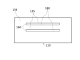
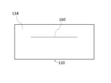
- the cut line 160 is formed on the side portion 134.
- the cut line 160 is formed along a single continuous line.
- the cut line 160 is a perforation.
- the cut line 160 includes a vertical cut portion 161 (first vertical cut portion), a vertical cut portion 162 (second vertical cut portion), and a horizontal cut portion 163.
- the cut line 160 consists only of the vertical cut portion 161, the vertical cut portion 162, and the horizontal cut portion 163.
- the vertical cut portion 161 and the vertical cut portion 162, and the horizontal cut portion 163 are all straight.
- the vertical cut portion 161 and the vertical cut portion 162 extend in the height direction of the main body 110.
- the horizontal cut portion 163 connects one end of the vertical cut portion 161 and one end of the vertical cut portion 162.
- One end of vertical cut portion 161 and one end of vertical cut portion 162 are located in the middle of side portion 134.
- the other end of vertical cut portion 161 and the other end of vertical cut portion 162 are also located in the middle of side portion 134.
- the middle of side portion 134 refers to the part other than the edge of side portion 134 (the boundary with bottom portion 120, the boundaries with each side portion 136, 138, and the boundary with top portion 140).
- Horizontal cut portion 163 extends parallel to bottom portion 120.
- Figures 9, 10, and 11 are respectively an oblique view, a plan view, and a side view of the main body 110 after deformation.
- Figure 9 is an oblique view seen from the bottom surface portion 120 side.
- Figure 11 is a side view seen from the side surface portion 132 side.
- Figure 12 is a diagram for explaining the structure of the end surface along line A-A in Figure 10.
- the tongue portion 170 is a portion that becomes the tongue portion 172 connected to the middle portion of the side portion 132 when a cut is made in the main body 110 (bottom portion 120 and side portion 132) along the cut line 150.
- the tongue portion 172 is composed of a single plate consisting of a part of the bottom portion 120 and a part of the side portion 132. In this embodiment, the shape of the tongue portion 172 is rectangular.
- the side portion 132 is provided with a fold line 133 for folding the tongue portion 172 toward the side portion 134.
- the fold line 133 is provided at a position that overlaps with the slit portion 180 described later in a side view.
- the fold line 133 connects the other end of the side cut portion 154 and the other end of the side cut portion 155.
- the fold line 133 is parallel to the bottom portion 120. It is preferable that a fold line 133 is pre-formed in the fold line 133 so that the tongue portion 172 can be easily folded along the fold line 133. However, the fold line 133 may simply consist of a line printed on the side portion 132 to inform the user of the fold position.
- the length of the tongue 172 is preferably 1.1 times or more, more preferably 1.2 times or more, of the distance d10 (see FIG. 7) from the side portion 132 to the side portion 134.
- the length of the tongue 172 is preferably 1 cm or more larger than the distance d10, more preferably 2 cm or more larger.
- the length of the tongue 172 is the maximum dimension of the tongue 172 in the direction perpendicular to the side portion 132 when the tongue 172 is spread on a plane parallel to the bottom portion 120.
- the length of the tongue 172 is equal to the sum of the length d11 of each bottom cut portion 151, 152 and the length d12 of each side cut portion 154, 155.
- the width w11 of the tongue 172 is preferably 1/2 or more, more preferably 3/4 or more, of the width w10 of the side portion 132.
- the width w11 is the maximum dimension of the tongue 172 in the direction perpendicular to the side portion 136 and the side portion 138.
- the slit portion 180 is a portion that is located in the middle of the side portion 134 and that becomes a slit 182 into which the tongue piece 172 can be inserted when a cut is made in the main body 110 (side portion 134) along the cut line 160.
- the slit 182 is a horizontally long opening that extends parallel to the bottom portion 120.
- the tongue piece 172 is configured to be parallel to the bottom portion 120 when inserted into the slit 182.
- the side portion 134 is provided with a fold line 135 for folding the portion 180a surrounded by the cut line 160 (vertical cut portion 161, vertical cut portion 162, and horizontal cut portion 163) to the outside of the main body 110.
- the fold line 135 connects the other end of the vertical cut portion 161 to the other end of the vertical cut portion 162.
- the fold line 135 is parallel to the bottom portion 120. It is preferable that the fold line 135 has a crease formed in advance so that the portion 180a can be easily folded along the fold line 135. However, the fold line 135 may be simply a line printed on the side portion 134 to inform the user of the fold position.
- the distance h11 (see FIG. 8) from the bottom surface portion 120 to the slit portion 180 is equal to or greater than 1/2 of the height h10 of the main body 110.
- the distance from the bottom surface portion 120 to the fold line 133 (equal to the length d12 of each side cut portion 154, 155) is equal to or greater than 1/2 of the height h10.
- a cut is made in the main body 110 along the cut line 160.
- the portion 180a surrounded by the cut line 160 is folded outward along the fold line 135 to turn the slit portion 180 into a slit 182.
- a cut is made in the main body 110 along the cut line 150 to turn the tongue portion 170 into a tongue 172.
- the tongue 172 is inserted into the slit 182 while being folded toward the side portion 134 along the fold line 133. This allows the main body 110 to be deformed so that the tongue 172 is inserted into the slit 182 (see Figures 9 to 12).
- an item (tissue paper 190) is placed on the tongue 172 as shown in Figure 12.
- the paper tissues 190 can be smoothly removed from the removal opening even when there is only a small amount of paper tissues 190 remaining.
- the distance from the tongue piece 172 to the top surface 140 is 3 cm or more and 6 cm or less. Note that the paper tissues 190 are not shown in Figures 10 and 11.
- the protruding portion 172a of the tongue 172 is printed with letters or a design.
- the protruding portion 172a is a portion that protrudes from the slit 182 to the outside of the main body 110.
- the letters or design are printed on the top surface of the protruding portion 172a (the surface on the top surface portion 140 side).
- the character string "ABC” is printed on the top surface of the protruding portion 172a. This top surface corresponds to a part of the inner surface of the bottom surface portion 120 of the main body 110 before deformation.
- the protruding portion 172a may be printed with a promotional message or advertising slogan for the company.
- the content of the company promotional message could be, for example, an introduction to the company's efforts in addressing environmental issues.
- the specific portion 134a is a portion that overlaps with the tongue portion 170 (the portion of the tongue portion 170 that is present on the side portion 132) in a side view.
- the character string "XYZ" is printed on the specific portion 134a.
- the character string is not shown.
- An advertising slogan may be printed on the specific portion 134a.
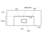
- the scented section 112 may be provided in the lower part 110a of the inner surface of the main body 110, as shown in FIG. 13, for example.
- the lower part 110a is a part that exists below the tongue piece 172 when inserted into the slit 182.
- the lower part 110a is composed of a part of the inner surface of the bottom part 120 and a part of the inner surface of each side part 132, 134, 136, 138.
- the scented section 112 is provided in a specific part 134a that is a part of the lower part 110a.
- a fragrance is attached to the scented section 112.
- the scented section 112 can be realized, for example, by printing a fragrance on the lower part 110a.
- a peelable sticker 114 is attached to the scented section 112.
- peelable means that the sticker 114 can be easily peeled off from the scented section 112 without damaging the lower part 110a and the scented section 112.
- the seal 114 prevents the fragrance in the scent section 112 from escaping.
- the tongue portion 170 and the slit portion 180 are provided on the main body 110.
- the tongue portion 170 provides a tongue 172 connected to the middle portion of the side portion 132.
- the slit portion 180 provides a slit 182 that is located in the middle portion of the side portion 134 and into which the tongue 172 can be inserted. By inserting the tongue 172 into the slit 182, the tongue 172 can be stretched from the middle portion of the side portion 132 to the middle portion of the side portion 134.
- the tongue 172 can be inserted into the slit 182 so that the item is placed on the tongue 172, and the bottom of the item storage box 2 can be raised while the tongue 172 is in surface contact with the item. Therefore, an item storage box 2 that can stably support items when the bottom is raised is realized without providing a bottom-raising member separate from the main body 110.
- an item storage box In an item storage box, storing as many items as possible is advantageous in terms of keeping the price per item down.
- the height of the main body In order to increase the number of items that can be stored in one item storage box, the height of the main body must be increased. Normally, when the height of the main body is increased, there is a problem that it becomes difficult to remove items when there are only a few items left. In this regard, with item storage box 2, which can be raised at the bottom, items can be easily removed even when there are only a few items left, so the above problem caused by increasing the height of main body 110 can be solved. Also, by increasing the height of main body 110, a large space can be secured for printing letters or patterns. Furthermore, since used main body 110 becomes garbage, storing a large number of items in one main body 110 also leads to a reduction in garbage.
- the tongue 172 is connected to the side portion 132 without being separated from the main body 110. In this case, a part of the tongue 172 is fixed to the side portion 132, which makes it difficult for the tongue 172 to accidentally come out of the slit 182.
- the tongue 172 is configured to be parallel to the bottom surface 120 when inserted into the slit 182. This also contributes to stable support of items in the item storage box 2 after the bottom has been raised.
- the distance h11 is equal to or greater than 1/2 of the height h10 of the main body 110.
- the distance h11 is equal to or less than 4/5 of the height h10.
- the side portion 132 has a fold line 133. This makes it easier to fold the tongue piece 172 neatly at the specified position.
- the fold line 133 is positioned so that it overlaps the slit portion 180 in a side view. This makes it easier to position the tongue piece 172 inserted into the slit 182 parallel to the bottom portion 120.
- the length of the tongue 172 is preferably 1.1 times or more, and more preferably 1.2 times or more, the distance d10 from the side portion 132 to the side portion 134. From the same perspective, the length of the tongue 172 is preferably 1 cm or more longer than the distance d10, and more preferably 2 cm or more longer. On the other hand, if the length of the tongue 172 is too large, it may be difficult to secure the tongue portion 170 in the main body 110 before deformation. From this perspective, the length of the tongue 172 is preferably 1.5 times or less than the distance d10. From the same perspective, the difference between the length of the tongue 172 and the distance d10 is preferably 5 cm or less.
- the cut line 150 is made up of bottom cut portions 151 to 153, as well as side cut portions 154 and 155. This allows the cut line 150 for forming the tongue piece 172 to be realized with a simple configuration.
- the bottom cut portions 151 and 152, and the side cut portions 154 and 155 are all in a straight line. This makes it easy to make cuts along the bottom cut portions 151, 152 and the side cut portions 154, 155.
- the bottom cutout portion 151 and the bottom cutout portion 152 extend perpendicular to the side portion 132. In this case, the length of each bottom cutout portion 151, 152 can be minimized. This also makes it easier to make cuts along each bottom cutout portion 151, 152.
- the side cut portions 154 and 155 extend in the height direction of the main body 110. In this case, the length of each side cut portion 154, 155 can be minimized. This also makes it easier to make cuts along each side cut portion 154, 155.
- the bottom cut portion 153 is in a straight line. This makes it easy to make cuts along the bottom cut portion 153.
- the bottom cutout portion 153 extends parallel to the side portion 132. This allows the dimensions of the tongue piece 172 in the direction perpendicular to the side portion 132 to be constant.
- the width w11 of the tongue 172 is advantageous for stably supporting items in the item storage box 2 after the bottom has been raised, since the tongue 172 will come into contact with a wider area of the item.
- the width w11 is preferably 1/2 or more of the width w10 of the side portion 132, and more preferably 3/4 or more.
- the width w11 is preferably 9/10 or less of the width w10.
- the width of side portion 132 and side portion 134 is greater than the width of side portion 136 and side portion 138.
- the cut line 160 includes vertical cut portions 161 and 162, as well as horizontal cut portions 163. This allows the cut line 160 for forming the slit 182 to be realized with a simple configuration.
- the vertical cut portions 161 and 162, and the horizontal cut portion 163 are all in a straight line. This makes it easy to make cuts along the vertical cut portions 161 and 162, and the horizontal cut portion 163.
- the cut line 160 consists only of the vertical cut portion 161, the vertical cut portion 162, and the horizontal cut portion 163.
- the portion 180a surrounded by the cut line 160 is not cut off from the main body 110, so it is possible to abut the portion 180a against the protruding portion 172a of the tongue piece 172. This makes it even more difficult for the tongue piece 172 to accidentally come out of the slit 182.
- Letter or a design is printed on the protruding portion 172a of the tongue piece 172.
- the aesthetic appearance of the body 110 after deformation can be improved.
- the letters or designs are printed on the top surface of the protruding portion 172a. By printing on the top surface, where they are easily visible, the letters or designs can be made to stand out.
- the outlet portion 172a can be used as advertising space. By recruiting advertisers, it is possible to earn advertising revenue. If this revenue is used to cover the manufacturing costs of the item storage box 2, the product price of the item storage box 2 can be kept low.
- Letter or a design is printed on the specific portion 134a on the inner surface of the side portion 134.
- the specific portion 134a can be used as advertising space. By recruiting advertisers, it is possible to earn advertising revenue. If this revenue is used to cover the manufacturing costs of the item storage box 2, the product price of the item storage box 2 can be reduced.
- the scent section 112 is provided on the lower portion 110a of the inner surface of the main body 110, it is possible to disperse a fragrance around the main body 110 after it has been deformed. In other words, by peeling off the seal 114 after the main body 110 has been deformed, the fragrance in the scent section 112 can be dispersed around the main body 110. In addition, because the seal 114 is affixed to the scent section 112, the user can choose whether or not to disperse a fragrance around the main body 110 by whether or not to peel off the seal 114.
- the specific section 134a is an easily accessible part of the lower section 110a, making it easy to peel off the seal 114.
- Other effects of the item storage box 2 are the same as those of the item storage box 1.
- the tongue 172 has a rectangular shape.
- the tongue 172 may have a tapered shape, for example, as shown in FIG. 14. In this case, it becomes easier to insert the tongue 172 into the slit 182.
- the horizontal cut portion 163 of the cut line 160 is shown as a straight line.
- the horizontal cut portion 163 may be wavy, for example, as shown in FIG. 15.
- the tongue piece 172 inserted into the slit 182 can be sandwiched from above and below by the convex portions, making it even more difficult for the tongue piece 172 to accidentally slip out of the slit 182.
- the main body 110 may have a plurality of slit portions 180, for example, as shown in FIG. 16.
- the plurality of slit portions 180 are provided at different positions in the height direction of the main body 110.
- a plurality of fold lines 133 are provided on the side portion 132, as shown in FIG. 17.
- the plurality of fold lines 133 are provided at different positions in the height direction of the main body 110.
- Each fold line 133 is provided at a position overlapping each slit portion 180 in a side view.
- the fold line 133 provided on the upper side of the side portion 132 overlaps the slit portion 180 provided on the upper side of the side portion 134
- the fold line 133 provided on the lower side of the side portion 132 overlaps the slit portion 180 provided on the lower side of the side portion 134.
- the height of the tongue 172 (the distance from the bottom surface 120) can be adjusted by selecting which slit 182 the tongue 172 is inserted into. This makes it possible to select the degree of bottom raising depending on the remaining amount of items. Also, by providing multiple fold lines 133, the tongue 172 can be more easily positioned parallel to the bottom surface 120 regardless of which slit 182 the tongue 172 is inserted into.
- the cut line 160 is located below the fold line 135.
- the cut line 160 may be located above the fold line 135, as shown in FIG. 18.
- the cut line 160 is formed along a single non-circular line.
- the cut line 160 may be formed along a single circular line, as shown in FIG. 19, for example.
- the portion 180a surrounded by the cut line 160 is cut off from the side portion 134, and a slit 182 having the same shape and size as the portion 180a is obtained.
- the cut line 160 is formed along multiple line segments.
- the cut line 160 may be formed along a single line segment, for example, as shown in FIG. 20. In the figure, the cut line 160 is entirely in a straight line.
- the cut lines 150 and 160 are perforations. That is, the cut lines 150 and 160 are configured such that the cuts are made along the cut lines 150 and 160 only when force is applied to both sides of the cut lines 150 and 160. However, the cut lines 150 and 160 may be made in advance. Third Embodiment
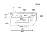
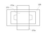
- FIGS. 21 and 22 are perspective views showing a third embodiment of an item storage box according to the present invention.
- FIG. 23 is a bottom view showing the third embodiment of an item storage box according to the present invention.
- FIGS. 24 and 25 are side views showing the third embodiment of an item storage box according to the present invention.
- the item storage box 3 is an item storage box in which multiple items are stored in a stacked state, and includes a main body 210.
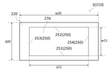
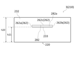
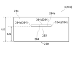
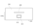
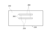
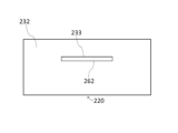
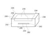
- the main body 210 is box-shaped and is composed of a bottom surface portion 220, a side surface portion 232 (first side surface portion), a side surface portion 234 (second side surface portion), a side surface portion 236 (third side surface portion), a side surface portion 238 (fourth side surface portion), and a top surface portion 240.
- the main body 210 is rectangular parallelepiped-shaped.
- Figures 21 and 22 are oblique views seen from the top surface portion 240 side and the bottom surface portion 220 side, respectively.
- Figures 24 and 25 are side views seen from the side surface portion 232 side and the side surface portion 234 side, respectively.
- the side surface portion 232 and the side surface portion 234 face each other.
- the side surface portion 236 and the side surface portion 238 also face each other.
- the widths of the side surface portion 232 and the side surface portion 234 are greater than the widths of the side surface portion 236 and the side surface portion 238.
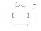
- the top surface portion 240 is provided with an outlet forming portion 20.
- the configuration of the outlet forming section 20 is as described in the first embodiment. However, in this embodiment, detailed illustration of the outlet forming section 20 is omitted.
- the main body 210 is configured so that it can be deformed into a bottom-up state.
- the main body 210 can be made of, for example, cardboard or other paper.
- the main body 210 has a cut line 250 (first cut line), a cut line 262 (second cut line), a cut line 264 (third cut line), a cut piece portion 270, a slit portion 282 (first slit portion), and a slit portion 284 (second slit portion).
- the cut line 250 is formed on at least one of the bottom surface portion 220, the side surface portion 232, and the side surface portion 234. In this embodiment, the cut line 250 is formed only on the bottom surface portion 220.
- the cut line 250 is formed along a single circular line as shown in FIG. 23.
- the cut line 250 is a perforation.
- the cut line 250 consists of a cut portion 251 (first cut portion), a cut portion 252 (second cut portion), a cut portion 253 (third cut portion), and a cut portion 254 (fourth cut portion). Cutout portion 251 and cutout portion 252 are in a straight line. In this embodiment, cutout portion 253 and cutout portion 254 are also in a straight line.
- the cutout portions 251 and 252 extend parallel to the side surface portion 232.
- the cutout portion 253 connects one end of the cutout portion 251 to one end of the cutout portion 252.
- One end of the cutout portion 251 and one end of the cutout portion 252 are located in the middle of the bottom surface portion 220.
- the middle of the bottom surface portion 220 refers to the portion of the bottom surface portion 220 other than the edge (the boundary with each of the side surface portions 232, 234, 236, and 238).
- the cutout portion 254 connects the other end of the cutout portion 251 to the other end of the cutout portion 252.
- the other end of the cutout portion 251 and the other end of the cutout portion 252 are located in the middle of the bottom surface portion 220.
- the cutout portions 253 and 254 extend perpendicular to the side surface portion 232.
- the cut line 262 is formed on the side portion 232. As shown in FIG. 24, the cut line 262 is formed along a single continuous line.
- the cut line 262 is a perforation.
- the cut line 262 includes a vertical cut portion 262a (first vertical cut portion), a vertical cut portion 262b (second vertical cut portion), and a horizontal cut portion 262c.
- the cut line 262 consists only of the vertical cut portion 262a, the vertical cut portion 262b, and the horizontal cut portion 262c.
- the vertical cut portion 262a, the vertical cut portion 262b, and the horizontal cut portion 262c are all straight.
- the vertical cut portion 262a and the vertical cut portion 262b extend in the height direction of the main body 210.
- the horizontal cut portion 262c connects one end of the vertical cut portion 262a and one end of the vertical cut portion 262b.
- One end of the vertical cut portion 262a and one end of the vertical cut portion 262b are located in the middle of the side portion 232.
- the other end of the vertical cut portion 262a and the other end of the vertical cut portion 262b are also located in the middle of the side portion 232.
- the middle portion of the side portion 232 refers to the part other than the edge of the side portion 232 (the boundary with the bottom portion 220, the boundaries with each side portion 236, 238, and the boundary with the top portion 240).
- the horizontal cut portion 262c extends parallel to the bottom portion 220.
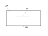
- the cut line 264 is formed on the side portion 234. As shown in FIG. 25, the cut line 264 is formed along a single continuous line.
- the cut line 264 is a perforation.
- the cut line 264 includes a vertical cut portion 264a (first vertical cut portion), a vertical cut portion 264b (second vertical cut portion), and a horizontal cut portion 264c.
- the cut line 264 consists only of the vertical cut portion 264a, the vertical cut portion 264b, and the horizontal cut portion 264c.
- the vertical cut portion 264a, the vertical cut portion 264b, and the horizontal cut portion 264c are all straight.
- the vertical cut portion 264a and the vertical cut portion 264b extend in the height direction of the main body 210.
- the horizontal cut portion 264c connects one end of the vertical cut portion 264a and one end of the vertical cut portion 264b.
- One end of the vertical cut portion 264a and one end of the vertical cut portion 264b are located in the middle of the side portion 234.
- the other end of the vertical cut portion 264a and the other end of the vertical cut portion 264b are also located in the middle of the side portion 234.
- the middle of the side portion 234 refers to the part other than the edge of the side portion 234 (the boundary with the bottom portion 220, the boundaries with each of the side portions 236 and 238, and the boundary with the top portion 240).
- the horizontal cut portion 264c extends parallel to the bottom portion 220.
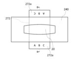
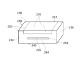
- FIGS. 26 and 27 are perspective views showing the main body 210 after deformation.
- FIGS. 26 and 27 are perspective views seen from the side portion 232 side and the side portion 234 side, respectively.
- FIGS. 28 and 29 are plan and bottom views, respectively, showing the main body 210 after deformation.
- FIG. 30 is a diagram for explaining the structure of the end face along line B-B in FIG. 28.
- the cut piece 270 is a portion that becomes the cut piece 272 when cut is made in the main body 210 (bottom surface portion 220) along the cut line 250.
- the cut piece 272 is made of a single plate that is a part of the bottom surface portion 220. In this embodiment, the shape of the cut piece 272 is rectangular.
- the length d21 of the segment 272 is preferably 1.2 times or more, more preferably 1.4 times or more, of the distance d20 from the side portion 232 to the side portion 234.
- the length d21 is preferably 2 cm or more larger than the distance d20, more preferably 4 cm or more larger.
- the length d21 is, for example, 14 cm or more and 20 cm or less.
- the length d21 is the maximum dimension of the segment 272 in the insertion direction of the segment 272 into the slit portion 282 and the slit portion 284 described later.
- the length d21 is equal to the length of each of the cut portions 251, 252.
- the width w21 of the segment 272 is preferably 1/4 or more, more preferably 1/2 or more, of the width w20 of the side portion 232.
- the width w21 is, for example, 6 cm or more and 10 cm or less.
- the width w21 is the maximum dimension of the segment 272 in the direction perpendicular to the insertion direction. In this embodiment, width w21 is equal to the length of each cutout portion 253, 254.
- the slit portion 282 is a portion that becomes a slit 283 (first slit) located in the middle of the side portion 232 and into which the piece 272 can be inserted when the main body 210 (side portion 232) is cut along the cut line 262.
- the slit 283 is a horizontally long opening that extends parallel to the bottom portion 220.
- the side portion 232 is provided with a fold line 233 for folding the portion 282a surrounded by the cut line 262 (vertical cut portion 262a, vertical cut portion 262b, and horizontal cut portion 262c) to the outside of the main body 210.
- the fold line 233 connects the other end of the vertical cut portion 262a to the other end of the vertical cut portion 262b.
- the fold line 233 is parallel to the bottom portion 220. It is preferable that the fold line 233 has a fold line formed in advance so that the portion 282a can be easily folded along the fold line 233. However, the fold line 233 may simply consist of a line printed on the side portion 232 to inform the user of the fold position.
- the slit portion 284 is a portion that becomes a slit 285 (second slit) located in the middle of the side portion 234 and into which the segment 272 can be inserted when the main body 210 (side portion 234) is cut along the cut line 264.
- the slit 285 is a horizontally long opening that extends parallel to the bottom portion 220.
- the segment 272 is configured to be parallel to the bottom portion 220 when inserted into the slit 283 and the slit 285.
- the side portion 234 is provided with a fold line 235 for folding the portion 284a surrounded by the cut line 264 (vertical cut portion 264a, vertical cut portion 264b, and horizontal cut portion 264c) to the outside of the main body 210.
- the fold line 235 connects the other end of the vertical cut portion 264a to the other end of the vertical cut portion 264b.
- the fold line 235 is parallel to the bottom portion 220. It is preferable that the fold line 235 has a crease formed in advance so that the portion 284a can be easily folded along the fold line 235. However, the fold line 235 may be simply a line printed on the side portion 234 to inform the user of the fold position.
- the distance h21 (see FIG. 24) from the bottom surface portion 220 to the slit portion 282 is equal to or greater than 1/2 of the height h20 of the main body 210.
- the distance h22 (see FIG. 25) from the bottom surface portion 220 to the slit portion 284 is equal to or greater than 1/2 of the height h20.
- the slit portion 282 and the slit portion 284 are formed at positions that overlap each other in a side view.
- a cut is made in the main body 210 along the cut line 262. Then, the portion 282a surrounded by the cut line 262 is folded outward along the fold line 233 to turn the slit portion 282 into a slit 283. Also, a cut is made in the main body 210 along the cut line 264. Then, the portion 284a surrounded by the cut line 264 is folded outward along the fold line 235 to turn the slit portion 284 into a slit 285. Next, a cut is made in the main body 210 along the cut line 250 to separate the cut portion 270 from the main body 210, turning the cut portion 270 into a cut portion 272.
- the cut portion 272 is inserted into the slit 283 and the slit 285 so that its short side is parallel to the side portion 232.
- the protruding portion 272a of the segment 272 is printed with letters or a design.
- the protruding portion 272a is a portion that protrudes from each slit 283, 285 to the outside of the main body 210.
- the letters or design are printed on the upper surface (the surface on the upper surface portion 240 side) of the protruding portion 272a.
- the character string "ABC” is printed on the upper surface of the protruding portion 272a.
- the upper surface corresponds to a part of the inner surface of the bottom surface portion 220 of the main body 210 before deformation.
- the protruding portion 272a may be printed with a promotional message or a promotional slogan such as a company PR message or an advertisement.
- the content of the company PR message may be, for example, an introduction to the company's efforts in addressing environmental issues.
- the lower portion 210a is the portion that exists below the piece 272 when it is inserted into the slits 283 and 285.
- the lower portion 210a consists of a part of the inner surface of the bottom portion 220 and a part of the inner surface of each of the side portions 232, 234, 236, and 238.
- An advertising slogan may be printed on the lower portion 210a.
- the lower portion 210a may be provided with a scented section 212, as shown in FIG. 31, for example.
- the scented section 212 is provided on the inner surface of the side portion 234.
- a fragrance is attached to the scented section 212.
- the scented section 212 can be realized, for example, by printing the fragrance on the lower portion 210a.
- a peelable sticker 214 is attached to the scented section 212.
- peelable means that the sticker 214 can be easily peeled off from the scented section 212 without damaging the lower portion 210a and the scented section 212.
- the sticker 214 prevents the fragrance in the scented section 212 from dissipating.
- the section 270, as well as the slit section 282 and the slit section 284 are provided on the main body 210. From the section 270, the section 272 separated from the main body 210 is obtained. From the slit section 282 and the slit section 284, the slit 283 and the slit 285 are obtained, which are located in the middle of the side section 232 and the side section 234, respectively, and into which the section 272 can be inserted. By inserting the section 272 into the slit 283 and the slit 285, the section 272 can be stretched from the middle of the side section 232 to the middle of the side section 234.
- an item storage box 3 has been realized that can stably support items when the bottom is raised, without the need for a bottom-raising member separate from the main body 210.
- an item storage box In an item storage box, storing as many items as possible is advantageous in terms of keeping the price per item down.
- the height of the main body In order to increase the number of items that can be stored in one item storage box, the height of the main body must be increased. Normally, when the height of the main body is increased, there is a problem that it becomes difficult to remove items when there are only a few items left. In this regard, with item storage box 3, which can be raised at the bottom, items can be easily removed even when there are only a few items left, so the above problem caused by increasing the height of main body 210 can be solved. Also, by increasing the height of main body 210, a large space can be secured for printing letters or patterns. Furthermore, used main body 210 becomes waste, so storing a large number of items in one main body 210 also leads to a reduction in waste.
- the segment 272 is in a state where it is separated from the main body 210. In this case, the segment 272 can be freely displaced relative to the main body 210, making it easier to insert the segment 272 into the slits 283 and 285.
- the distance h21 is equal to or greater than 1/2 of the height h20 of the main body 210.
- the distance h21 is equal to or less than 4/5 of the height h20.
- Increasing the distance h22 from the bottom surface portion 220 to the slit portion 284 in the height direction of the main body 210 is advantageous in terms of enhancing the bottom-raising effect of the item storage box 3. From this perspective, it is preferable that the distance h22 is equal to or greater than 1/2 of the height h20 of the main body 210. On the other hand, if the distance h22 is too large, the amount of items that can be stored in the item storage box 3 after deformation will be extremely small. From this perspective, it is preferable that the distance h22 is equal to or less than 4/5 of the height h20.
- Slit portion 282 and slit portion 284 are formed in a position where they overlap each other in a side view. This makes it easier to position piece 272 inserted into slits 283 and 285 parallel to bottom portion 220.
- the cut lines 250 are formed only on the bottom surface 220. In this case, the cut lines 250 do not pass through the boundaries between the bottom surface 220 and each of the side surfaces 232, 234, 236, and 238, making it easier to make cuts along the cut lines 250.
- the cut line 250 is made up of cut portions 251 and 252, as well as cut portions 253 and 254. This allows the cut line 250 for forming the segment 272 to be realized with a simple configuration.
- the cut portions 251 and 252 are in a straight line. This makes it easier to make cuts along the cut portions 251 and 252.
- the cut portions 253 and 254 are in a straight line. This makes it easier to make cuts along the cut portions 253 and 254.
- the width w21 of the segment 272 is advantageous for stably supporting the item in the item storage box 3 after the bottom has been raised, since the segment 272 will come into contact with a wider area of the item.
- debris from the item e.g., paper dust from tissue paper
- the width w21 is preferably 1/4 or more of the width w20 of the side portion 232, and more preferably 1/2 or more.
- the width w21 is preferably 3/4 or less of the width w20.
- the vertical cut portions 262a and 262b, and the horizontal cut portion 262c are all in a straight line. This makes it easy to make cuts along the vertical cut portions 262a and 262b, and the horizontal cut portion 262c.
- the cut line 262 consists only of the vertical cut portion 262a, the vertical cut portion 262b, and the horizontal cut portion 262c.
- the portion 282a surrounded by the cut line 262 is not cut off from the main body 210, so it is possible to abut the portion 282a against the protruding portion 272a of the piece 272. This makes it even more difficult for the piece 272 to accidentally slip out of the slit 283.
- the cut line 264 includes vertical cut portions 264a and 264b, as well as horizontal cut portions 264c. This allows the cut line 264 for forming the slit 285 to be realized with a simple configuration.
- the vertical cut portions 264a and 264b, and the horizontal cut portion 264c are all in a straight line. This makes it easy to make cuts along the vertical cut portions 264a and 264b, and the horizontal cut portion 264c.
- the cut line 264 consists only of the vertical cut portion 264a, the vertical cut portion 264b, and the horizontal cut portion 264c.
- the portion 284a surrounded by the cut line 264 is not cut off from the main body 210, so it is possible to abut the portion 284a against the protruding portion 272a of the piece 272. This makes it even more difficult for the piece 272 to accidentally slip out of the slit 285.
- Letter or a design is printed on the protruding portion 272a of the segment 272.
- the aesthetic appearance of the body 210 after deformation can be improved.
- the letters or designs are printed on the top surface of the protruding portion 272a. By printing on the top surface, where they are easily visible, the letters or designs can be made to stand out.
- the outlet portion 272a can be used as advertising space. By recruiting advertisers, it is possible to earn advertising revenue. If this revenue is used to cover the manufacturing costs of the item storage box 3, the product price of the item storage box 3 can be kept low.
- the lower portion 210a can be used as advertising space. By recruiting advertisers, it is possible to earn advertising revenue. If this revenue is used to cover the manufacturing costs of the item storage box 3, the product price of the item storage box 3 can be kept low.
- the fragrance section 212 is provided in the lower portion 210a, it is possible to disperse a fragrance around the main body 210 after it has been deformed. That is, by peeling off the seal 214 after the main body 210 has been deformed, the fragrance in the fragrance section 212 can be dispersed around the main body 210. In addition, because the seal 214 is affixed to the fragrance section 212, the user can choose whether or not to disperse a fragrance around the main body 210 by whether or not to peel off the seal 214. Other effects of the item storage box 3 are the same as those of the item storage box 1.
- the horizontal cut portion 262c of the cut line 262 is shown as a straight line.
- the horizontal cut portion 262c may be wavy, for example, as shown in FIG. 33.
- the piece 272 inserted into the slit 283 can be sandwiched from above and below by the convex portions, making it even more difficult for the piece 272 to accidentally slip out of the slit 283.
- the main body 210 may have a plurality of slit portions 282 and a plurality of slit portions 284, as shown in, for example, FIG. 35 and FIG. 36.
- the plurality of slit portions 282 are provided at different positions in the height direction of the main body 210.
- the plurality of slit portions 284 are provided at different positions in the height direction of the main body 210.
- the slit portions 282 and the slit portions 284 are provided at positions overlapping each other in a side view.
- the height of the segment 272 (the distance from the bottom surface 220) can be adjusted by inserting the segment 272 into whichever pair of slits 283, 285. This makes it possible to select the degree of bottom raising depending on the remaining amount of items. Also, by arranging each slit 282 and each slit 284 in a position where they overlap each other in a side view, it becomes easier to position the segment 272 parallel to the bottom surface 220 regardless of which pair of slits 283, 285 the segment 272 is inserted into.
- the cut line 262 is formed along a single non-circular line.
- the cut line 262 may be formed along a single circular line, for example, as shown in FIG. 39.
- the portion 282a surrounded by the cut line 262 is cut off from the side portion 232, and a slit 283 having the same shape and size as the portion 282a is obtained.
- Figure 45 is an oblique view of the main body 210 in Figure 44 as seen from the opposite side (the side surface portion 234 side).
- the cut piece 272 is formed from a single plate consisting of a part of the bottom surface portion 220, a part of the side surface portion 232, and a part of the side surface portion 234.
- Forming the cut line 250 from the bottom surface portion 220 to the side surface portion 232 in this manner is advantageous for increasing the width of the segment 272.
- Forming the cut line 250 from the bottom surface portion 220 to both the side surface portion 232 and the side surface portion 234 is particularly advantageous for increasing the width of the segment 272.
- the cut line 250 may be formed only on the side surface portion 232 or only on the side surface portion 234.
- the present invention is not limited to the above embodiment, and various modifications are possible.
- the cut line 42 is wavy.
- the cut line 42 may be straight, as shown in FIG. 46. In this case, it becomes easier to make the cuts along the cut line 42.
- the cut lines 42, 44, and 46 are perforations.
- the cut lines 42, 44, and 46 are configured so that cuts are made along the cut lines 42, 44, and 46 only when force is applied to both sides of the cut lines 42, 44, and 46.
- the cut lines 42, 44, and 46 may be pre-cut.
- both the fold line 32 and the fold line 34 are curved.
- only one of the fold line 32 or the fold line 34 may be curved.
- the fold line 32 is curved and bulges outward from the folded piece 22, while the fold line 34 is straight.
Landscapes
- Engineering & Computer Science (AREA)
- Mechanical Engineering (AREA)
- Cartons (AREA)
Priority Applications (2)
| Application Number | Priority Date | Filing Date | Title |
|---|---|---|---|
| PCT/JP2024/012307 WO2024117271A2 (ja) | 2024-03-27 | 2024-03-27 | 物品収納箱 |
| JP2024519502A JPWO2024117271A1 (en]) | 2024-03-27 | 2024-03-27 |
Applications Claiming Priority (1)
| Application Number | Priority Date | Filing Date | Title |
|---|---|---|---|
| PCT/JP2024/012307 WO2024117271A2 (ja) | 2024-03-27 | 2024-03-27 | 物品収納箱 |
Publications (2)
| Publication Number | Publication Date |
|---|---|
| WO2024117271A2 true WO2024117271A2 (ja) | 2024-06-06 |
| WO2024117271A3 WO2024117271A3 (ja) | 2024-07-25 |
Family
ID=91323937
Family Applications (1)
| Application Number | Title | Priority Date | Filing Date |
|---|---|---|---|
| PCT/JP2024/012307 WO2024117271A2 (ja) | 2024-03-27 | 2024-03-27 | 物品収納箱 |
Country Status (2)
| Country | Link |
|---|---|
| JP (1) | JPWO2024117271A1 (en]) |
| WO (1) | WO2024117271A2 (en]) |
Family Cites Families (7)
| Publication number | Priority date | Publication date | Assignee | Title |
|---|---|---|---|---|
| JPS62132970U (en]) * | 1986-02-17 | 1987-08-21 | ||
| JPH0387690U (en]) * | 1989-12-22 | 1991-09-06 | ||
| JPH0480878U (en]) * | 1990-11-28 | 1992-07-14 | ||
| JPH04112073U (ja) * | 1991-03-13 | 1992-09-29 | 株式会社マルト長谷川工作所 | テツシユペーパー用ホルダー |
| JPH1086981A (ja) * | 1996-09-12 | 1998-04-07 | Tsutomu Tanizawa | 落ち止めボックス |
| JPH11314687A (ja) * | 1998-05-01 | 1999-11-16 | Toshio Saito | 内容物の残量の安定取り出し可能箱 |
| JP2009184719A (ja) * | 2008-02-08 | 2009-08-20 | Daiki:Kk | 取出口片を蓋として使用するティッシュペーパーボックス |
-
2024
- 2024-03-27 WO PCT/JP2024/012307 patent/WO2024117271A2/ja unknown
- 2024-03-27 JP JP2024519502A patent/JPWO2024117271A1/ja active Pending
Also Published As
| Publication number | Publication date |
|---|---|
| WO2024117271A3 (ja) | 2024-07-25 |
| JPWO2024117271A1 (en]) | 2024-06-06 |
Similar Documents
| Publication | Publication Date | Title |
|---|---|---|
| CN1144742C (zh) | 纸巾盒 | |
| US4925087A (en) | Packaging container with display window | |
| JP7714203B2 (ja) | 物品収納箱 | |
| WO2024117271A2 (ja) | 物品収納箱 | |
| JP5534462B2 (ja) | スタンド付ティッシュペーパーボックス | |
| JP4515152B2 (ja) | 表示機能を有する衛生用紙入りカートン | |
| USRE38696E1 (en) | Pop-up advertising piece | |
| US6474542B1 (en) | Carton with framed opening feature and product viewing window | |
| WO2024167028A2 (ja) | 物品収納箱 | |
| US7090096B2 (en) | Easel sheet dispenser | |
| WO2024090588A2 (ja) | 物品収納箱 | |
| US20060060641A1 (en) | Presentation folder | |
| WO2024085262A2 (ja) | 物品収納箱 | |
| JP4008259B2 (ja) | 商品収納構造および商品収納方法 | |
| JP2003261135A (ja) | 陳列箱 | |
| JP7296286B2 (ja) | 包装箱 | |
| JP7261025B2 (ja) | 什器転用型化粧箱 | |
| JP2025007072A (ja) | 紙製容器 | |
| JPH0245138Y2 (en]) | ||
| CN111086723A (zh) | 成对消费品的电子商务包装系统 | |
| JP4183136B2 (ja) | 包装用ケース | |
| WO2025037652A2 (ja) | 物品収納箱 | |
| JP4917568B2 (ja) | 包装用ケース | |
| EP0098107A2 (en) | Display cartons | |
| JP2024157779A (ja) | 紙製容器 |
Legal Events
| Date | Code | Title | Description |
|---|---|---|---|
| ENP | Entry into the national phase |
Ref document number: 2024519502 Country of ref document: JP Kind code of ref document: A |
|
| 121 | Ep: the epo has been informed by wipo that ep was designated in this application |
Ref document number: 24729950 Country of ref document: EP Kind code of ref document: A2 |